Strange Blue Prints

Hey All! I’ve recently arrived from a trip in New York, and have got some photos.

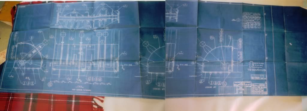
I took some photos of some strange blue prints that my grandfather was working on in WWII. I think that they are for American Aircraft, but I’m not sure. Could you tell me any information?

(Also, he HAD blueprints of the first postwar ICBM that he was working on with Wehrner Von Braun, but recycled them because they were ‘trash’ :evil: )

This is only speculation on my part, they do not look like the usual layout for throttles, but maybe for some other control surfaces. And may be part of the flight engineers staion. but as I say, just guessing. Otherwise could be marine in nature.

MoS you wanna take a stab at this?

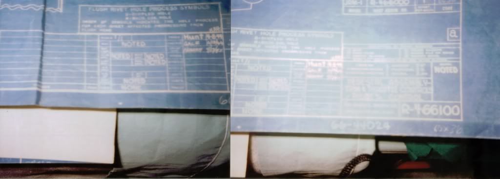
They do look vaguely like some form of throttle quadrant. Have you got any better photos of the bottom right hand corner of the drawing? Those ones are illegible, and that’s the critical part of the drawing…

Zooming in on Drawing No. R-466100, the drawing title says:

PEDESTAL ASSEMBLY
TRIM & THROTTLE CONTROLS
PILOT’S CONTROL

Sorry for the extremely low quality. I had to use an ancient actual film camera to take these photos. My grandfather will be sending the blue prints to me, so once I have them I’ll take higher resolution shots with a digital.

Sorry again

Ohhh, My hasselblad is sobbing in the corner, :smiley:

…What…? :confused:

The Hasselblad reference was an obscure film camera joke, “ancient,actual film camera”.

i have seen blue prints of the same sort of nature , but there were for LCTs and other amphibious landing craft that were being designed and built for the future D-Day Landings , its just a guess but it might the same sort of thing .

They’re unlikely to be described as “pilot’s control” however!

That’s a standard engineering drawing layout (still used today) with the only exception being that modern ones tend to be printed (black ink on white paper) rather than blueprinted as the cyanotype process has been replaced by the laser printer.

Yeah. This was done by hand.

I’ve never understood how they managed to do that day in, day out for years on end. After two hours at a drawing board doing this sort of thing I use the ability to see. Thank God for CAD!

My grandfather says it was like hell, and that his officers made him do it. Luckily, he had an unlimated number of stencils, tools, tracers, etc. of different sizes to aid him. He would make the original, and then copies would be made to send to factories, manfucaturing areas, etc.

Thing is that doesn’t actually help very much. The basic tools are drawing board, ruler on a set of rollers to keep it parallell, clips to hold the paper in, compasses, a kind of tilting set square (third side of the triangle is on a hinge that can be locked), pencil and eraser. The only other things I ever found useful are a kind of tin cutout that makes it easier to rub out only the line you got wrong, and a kind of bendy ruler that makes it easier to duplicate curves.

Drawing a simple view from one side of a part is easy. The problem is when you have to do three view projections, particularly of curved surfaces. The worst one I ever had to do was the intersection of a cone and a tube - if you get it right it looks rather like an apostrophe, but you have to spend hours on it just for that one projection.

(Incidentally, last I checked this was still being taught on the engineering course I did, despite nobody actually doing technical drawing for anything other than a hobby nowadays in the West - the skills you gain from knowing how to do it are actually rather useful in other areas.)

This is just drafting 101. Engineers of all kinds and architects and surveyors all did it. Some used parallel bars and others used “drafting machines” which were mounted horizontally on tensor-lamp type arms. The whole world was doing it so it was no big deal. Today, at least in the west, it’s all done on computers, but I spent years doing it the old way and found it satisfying in its own way - you could point to a beautiful drawing and say, “I did that”. It was a skill.

Computers allow you to do really professional looking drawings fairly quickly - but it’s like learning another language with a computer box in between you and the drawing and the drawings, which might look perfect and professional, can be just as wrong only you would be deluded into thinking that they are just right.

The current rage in the field is BIM - Building Information Modeling - which is considerably smarter than a simple cadd - computer-aided design and drafting - drawing meaning that the “drawing” is really a database file that can be manipulated to give you 3D views, building material tables, specifications, cost estimates, and all sorts of design tools. Eventually everyone will be doing it in part because it 1) saves time, 2) saves money (the real reason), 3) increases accuracy (so long as you don’t override dimensions calculated by the computer) and 4) improves coordination among architects and all his/her consultant team members by ferreting out conflicts among structure, finishes, lighting, ductwork clearances, raceway clearances, etc.

Lastly, the contractors want this because they want to use the BIM files to prepare their shop drawings, which could be dangerous because a perfect set of drawings doesn’t exist and the general contractor will be tempted to rely on dimensions which he should be exhaustively checking on his own. Contractors, if they are going to receive the BIM files, should pay for them because it will save them gobs of money by using drawings and databases prepared by the design team.
'Nuff said!
Yeah, there are all sorts of funky things you can do with modern CAD systems. We use Catia v5 at work, and there are all sorts of things like Monte Carlo tolerance analysis that it can do automatically which are a major pain in the backside when done by hand.

Where I work we are using AutoCAD version 2005 thru 2008. (.dwg file format)

I have used the Microstation / Intergraph CAD program for a number of years also. (IGDS - Interactive Graphics Design System) .dgn file format.

Back in the 1940’s many drawings were done with ink on linen. I have seen actual blueprints dating back to the early 1920’s thru 1940’ and 50’s. One set of prints were for some storage buildings at Jax NAS (Jacksonville Naval Air Station in 1943) These particular buildings were built by German POW’s captured in North Africa. I have seen the buildings inside and out first hand. The wood roof framing visible from the interior looked almost new.

CAD has a great advantage in speed, especially in making revisions. Most of the standard components such a structural steel shapes like I-Beams are already available pre-drawn to exact size (ex: W10x22) and can be simply inserted into the drawings where needed. Makes drawings more accurate.