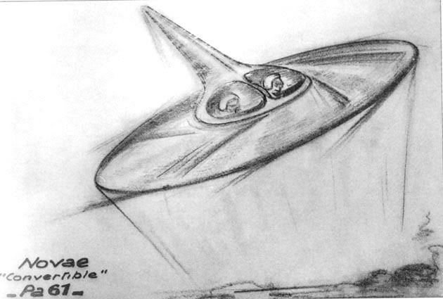
Sorry for my pretty late answer, my dear Herr Major, but I was under objective necessity to consult some valid scientific resources. I hope that these technological fragments will be usable for you. 
But, I mean is it possible for a Flugelrad to work? Are the designs plausible? would torque be a problem?
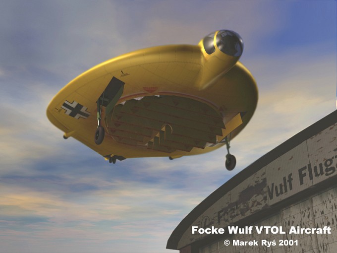
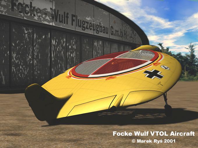
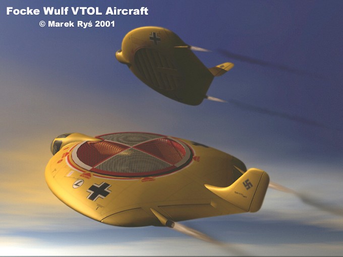
Yes, my dear Major: theoretically, this Flügelrad machine represents an achievable, but in the very same time fairly problematical solution.
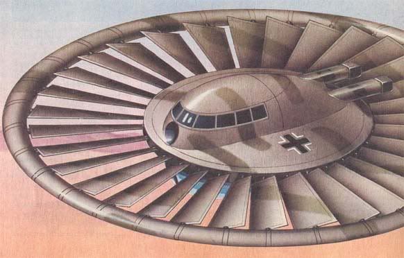
Basically, it is a rotary wing aircraft- which means that it has a rotor to provide lift instead of wings, like conventional airplanes. However, unlike a helicopter, this rotor is not powered directly by the engine shaft, but by a so-called jet-stream blown fan - in theory also known as Fan-In-Fuselage Rotary Wing – that practically deflects the jet engine exhaust to gain rotation of the fan, thus actually increasing the net thrust obtained from the diverted flow by using the energy of the exhaust to accelerate a larger mass of air. This on the other side augments thrust by increasing the net propulsive efficiency.
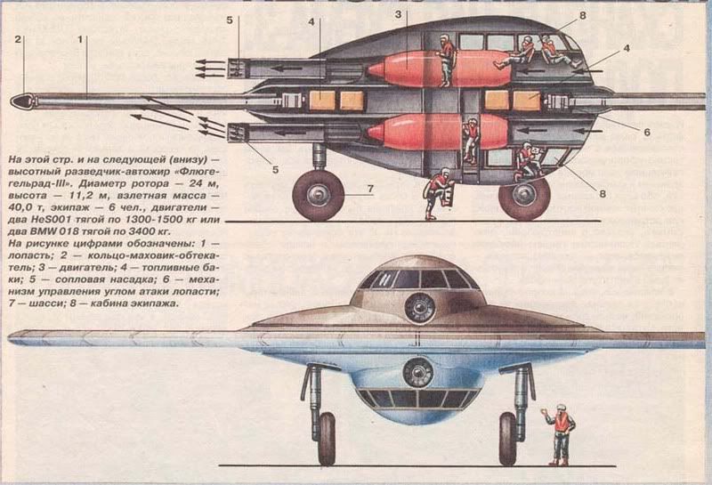
Exhaust gases are turning sort of a ducted fan - the diverted engine exhaust is passed over the rotor blades to spin the complete fan. In this case, you will be able – at least theoretically! - to achieve a so called airflow augmentation ratio of almost three (the lifting thrust will be circa three times bigger than the thrust produced by the jet engines during normal forward flight (more realistic value, however, probably ranges from about 1.3 to perhaps 2.2).
Nevertheless - and as already correctly observed by you - this solution indeed produces vastly unbalanced rotor torque. To avoid produced torque of the rotor, the best solution is to have two of them, rotating in the opposite directions, but in our case this is hardly achievable. Fan is heavy and completely integrated into the main structure, thus being very bulky and unfit for counter-balancing, due to great oscillation masses, and with a continuing alloy thermal stability problems too. The only theoretical advantage in this case is that fan generally tends to reduce the thrust-matching problem, since the engines in this case do not have to be sized to lift the machine by jet thrust alone.
Of course, gyroscopic stabilization is another possibility, but it is inevitability a heavyweight solution, with all negative repercussions toward effective payload, range and structural rigidity.
On the other hand, the transition from vertical to forward flight remains a complete mystery, because thrust-matching problem during transition flight is not clearly resolved. Although vectoring flaps are part of the engine’s exhaust, it is not clear how this solution will be able to turn the engine flow more than 15 degrees for completely different tasks of hovering and flight. Perhaps those fan-winglets are equipped with some kind of a fan-blade pitch adjustment mechanism (although I am not able to see any trace of it!), but in that case completely laminar, non-turbulent, optimized flow of the exhaust gases is not manageable. And as far as I can see potentially usable rotating jet-engine elbow exhausting nozzles are not prefigured as a suitable solution.
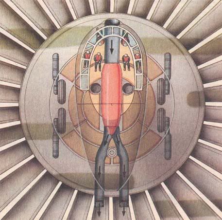
Another problem is present in a form of so-called suck-down and fountain-lift air circulation. You see, my dear Herr Major, a VTOL machine in hover is not positioned in the stagnant air. The vertical fan-vortex that supports the aircraft also accelerates the air mass around it. This entrainment exists due to viscosity of the air, and produces a downward flow-field around the aircraft.
This downward flow-field pushes down on the aircraft with a vertical drag force equivalent to a loss of 4-6% of the lift thrust. The magnitude of this “vertical drag” depends largely upon the relative location of the fan and the fuselage. If the completely bulky nacelle is, as in our case, in the centerplane of the machine, thus entrained airflow will exert a significant downward force.
The effect of the ground is another problem. The mass of the air, mixed with exhaust gases, strikes the ground and spreads outward. This increases the entrainment force, and the entrained download, (or suck-down) increases as the ground is approached. The strength of the air-fountain depends upon the exact arrangement of the fan and the shape of the fuselage, but generally round, almost completely planar and additionally circle-shaped fuselage makes it more difficult for the fountain to flow around the fuselage, and it will increase the fountain effect.
Of course, we are faced here with another class of problems as well: with recirculation and hot–gas ingestion. A jet-propelled VTOL machine while hovering near the ground tends to “drink its own bath-water”. The hot exhaust gasses are able to find their way back to the engine inlet, causing significant reduction in thrust. In addition, this recirculated air can include dirt and other abrasive particles that are completely capable to damage or destroy the complete engine. Furthermore, in some cases the dirt kicked up by a hovering aircraft can completely obscure the pilot’s vision.
However, these observations are representing only my theoretical remarks. Therefore, if you like this design, my dear Herr Major – no problem, let it be! After all, disc-shaped machines do have certain undisputable advantages: they can produce higher lift coefficients than other wings and they can be built lighter than conventional thin wings.
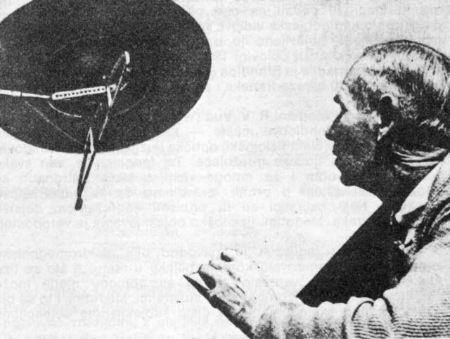
Previous designs suffered from very complex structures, but circular wing machines were able to produce some truly amazing achievements. For example, this tiny American machine produced by Dr. E. W. Kay was capable to rise from the ground like a helicopter and then to hurtle through the air at velocities of over 500 knots. Of course, nobody was interested… 
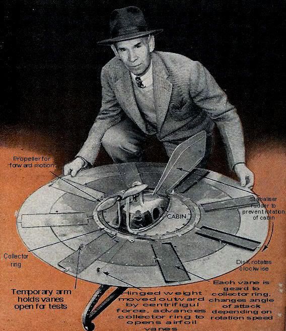
Gyro-disc, 1951
A very high lift coefficients, more useful internal volumes, and an ability to fly very slow were primary motives for some highly intriguing Soviet developments as well:
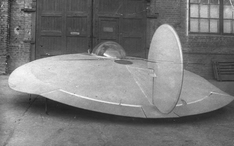
Discoplan, USSR - 1963.
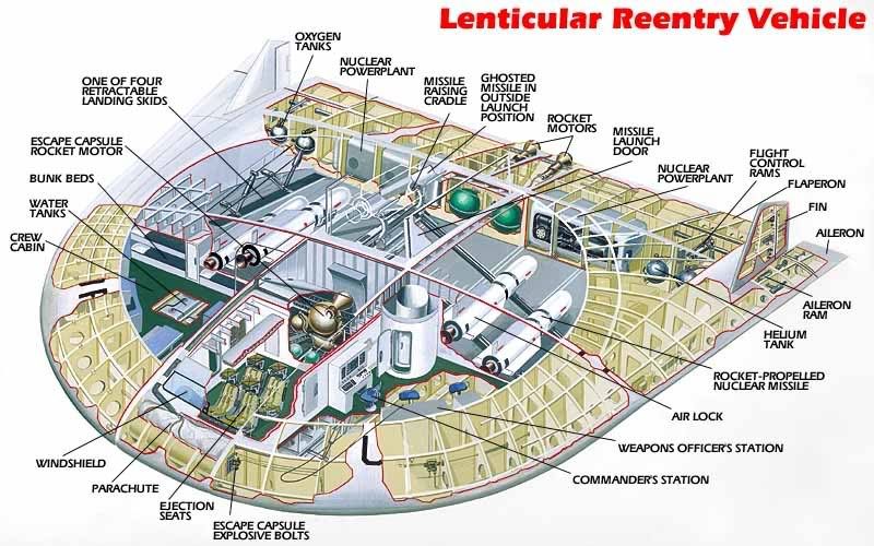
On the other hand, certain advantages of the circular wings embedded in high supersonic stability and lift even at extreme angles of attack, as well as evenly distributed aircraft mass made these solutions highly desirable for the anticipated soviet supersonic projects, like this one that was publicly presented in 1964.

Hypersonic Liner, USSR - 1964
But that, honorable ladies and gentlemen, is a completely different story…
In the meantime, as always – all the best! 




.jpg)
