Although Mr. David Smith was a steam turbine design engineer (sic!) within Metropolitan Vickers, he and other engeneers at the company were aware of the possibilities of the axial flow turbojet engine.
Originally, the first British axial-flow aircraft gas turbine B10 (known as Betty) was to have been built by the RAE (Royal Aircraft Establishment) the engines compressor was based on test data from experimental compressor “Anne” built to a design by A.A. Griffith of the RAE and manufactured by Fraser and Chalmers. A senior scientist within the RAE, A. A. Griffith had published paper on gas turbine development as early as 1926, and together with Hayne Constant, also of the RAE, considered that the compressors of future gas turbines should be of the axial type; However, the RAE did not have the manufacturing or research capability to make this aerodynamically complex compressor work on a scale sufficient to power an aircraft.
In 1937 discussions took place between the RAE and Metropolitan Vickers chief engineer Dr. Karl Baumann who in turn appointed Dr. David Smith to lead the design, development and manufacturing team. Work started at the company the following year under an Air Ministry Contract.
The experimental non-flight engine B10 had proved successful, with a compression ratio of 2:1. As war broke out and the Trafford Park Factory became committed to war work and space was at a premium, B10 had set fire to the research facility so it was decided to extend a small overspeed test cell which had been built in some secrecy on land off Barton Dock Road at Urmston, Manchester, with a view to relocate all gas turbine research and development. For a brief period the salt mines in Wincham had been used for engine testing, however pollution and fog from the nearby industrial town of Northwich caused contamination of the compressor blading which effected performance tests so all efforts were concentrated at “Barton Test’”.
The first flight engine F2 (“Freda”) ran in a test cell during December 1942, by June 1943 an F2 engine of 1800 lb static thrust was altitude tested in the tail of a Lancaster bomber. The Lancaster, which operated from the RAE Farnborough became the topic of much local discussion as it flew over the Manchester area. Interestingly, the aircraft allocated by the ministry was the Lancaster prototype which proved to be most unreliable, much to the frustration of Dr. Smith and the Metrovic team.
The first aircraft to be powered by and axial flow turbojet was a Gloster F/9 40 Meteor aircraft, the flight took place at the RAE on the 13th November 1943.
Metrovic continued turbojet development, the last flight engine being the F9 Sapphire, the design of which was handed to Armstong Siddley when Metropolitan Vickers decided to opt out of aircraft gas turbines and concentrate manufacturing and development on Industrial and Marine steam and gas turbines.
The test cells at Barton were turned over to steam turbine reseach and development in the early 1960’s. Dr. Smith returned to steam turbine design, although in great secrecy he was asked to assist Rolls-Royce’s Dr. Stanley Hooker when Rolls-Royce engineers ran into aerodynamic problems when developing the compressor for the famous Rolls-Royce Avon gas turbine engine.
It is worth noting that Whittle-type engines powered all the first generation of postwar jet aircraft…
Oh no, my dear Mr. Pdf 27. The MiG 9 “Fargo ” (first flight: April 24, 1946) was powered by two RD-20 jet engines (Soviet derivative of a BMW 003 A), and both Jak-15 and Jak 17 used a single RD 10 jet engine (Soviet version of a Jumo 004). You know… Just for the record.
RR Derwent instead is to me further evidence that your thesis that the Jumo-004 wasn’t too bad really does not hold water. It wasn’t until engines like the Armstrong-Siddely Sapphire and RR Avon became available in the 1950s that axial flow engines gained widespread acceptance.
Don’t be so sure, my dear Mr. Pdf 27. Those unknown masterpieces of engeneering produced back there in USSR are still widely unknown. Yes, you are right – they were not applied, more precisely not initially, but highly original constructive bureaus leaded by Stechkin and Mikulin actually have designed some very intriguing designs in early fifties. Yes, I know - this is not directly connected with WW2, but… Perhaps that will be a theme for another thread.
…and the only reason that they are nowadays limited to a few applications like helicopter engines is simply due to ducting problems when stacking compressors, rather than issues of frontal area.
Really, my dear Mr. Pdf27? Excellent. Allow me than a tiny proposal: let’s make a tiny mathematical exercise deeply connected with some standard engineering tasks in aeronautic industry. Would you be so kind to make for me the Constant outer engine intake diameter calculation [Dmax] (given as the equivalent flat-plate area), separately for an axial-compressor equipped, as well as for centrifugal compressor equipped engine, outfitted with the following common parameters:
• Inlet Mach number: 0.70
• stagnation pressure: 101.4 kPA
• Inlet stagnation temperature: 300 K
• Pressure ratio: 21
• Isentropic efficiency of the compressor: 0.85
• Isentropic efficiency of the turbine: 0.85
• Mechanical transmission efficiency between the turbine and compressor: 0.97
• Combustion chamber pressure loss factor: 0.06
• Static thrust of the engine: 72 kN
• Engine airflow: 65 kg/s.
After that, please recalculate the parasite drag value of different engines, and compare gained numerical results. I am pretty sure right now that an axial compressor engine would allow higher drag-efficiency at lower frontal areas, so vital for a modern aircraft, of course, with some sacrifice to weight and length.
And don’t worry – some personal friends of mine will land you a hand in this lastly mentioned task. We will do that in complete congruence with the prescription and methodology prescribed in a Educational Manual EM 910 – “Elements of Aeronautics”, by Francis Pope and Arthur S. Otis, United States Armed Forces Institute, Washington.
I really can’t see how the degree of reaction would substantially affect the reheat stage. All it does is change the design of the final stator.
Indeed wery good and truly matter oriented observation, my dear Mr. Pdf 27. Well, I have to admit that I was able to find no more than one possibility. Accordingly to Dr. Fritz Dietzel (“Gasturbinen”, Vogel Verlag, 1974, p. 251), the degree of reaction, as the numerical ratio of the static pressure change in the rotor to the static pressure change through the whole stage, would substantially affect the turbine and compressor blades upstreaming and thus the flow simmetricity within the rotor and stator blades, and as a consequence the constructive possibility for the employment of the identical constructive parts for the rotor and stator blades network. For example, the compressor stage with a degree of reaction of 0.5 would share the pressure rise about equally between the rotor and stator, so the application of standardized components in that case will be possible.
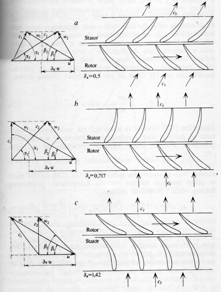
“Degree of reaction”, Dietzel, p.251
Accordingly to Dietzel, the degree of reaction amounts constructive complexity, possibility for constructive parts standardization, and therefore the employment of strategically critical materials.
However, knowing intrinsic and constant German engineering tendency toward thermodynamic conversion effectivity, my personal conviction is that the German constructors actually have contemplated about one specific, truly brilliant and even today sadly neglected technological solution. Namely this one:
Now, look carefully, my dear Mr. Pdf 27. Do you see that pretty peculiar component marked with No. 10, and located within the rear part of the engine?
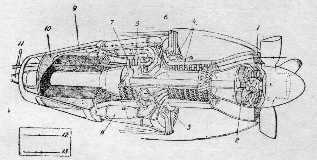
Mysterious Possibility
You do? Excellent. Can you guess the gadget? A little tip – in this case the degree of reaction is extremely important!
In the meantime, as always – all the best!


