Strange then that the UK produced more Tanks, ships and aircraft than germany isnt it.
hi there,
dont quote me on this but the engins that the me262 used were made by Heinkel, they both tryed to win the contract Messerschmitt won but usd the others engins, hitler wanted thei to be a bomber not a fighter so he too slowed down the making of this plane, and yes they did have trouble with the metals for the engins.
Please forgive me my unaccountably extended absence, honorable ladies and gentlemen, but due to my completely unforeseen professional obligations I was completely unable to participate in this more than inspiring conversation. However - better late then never.
The US jet programme contributed precisely nothing to the allied war effort.
Very intriguing and truly brave observation, my dear Mr. Pdf 27. However, allow me please just one additional question: What is your personal opinion about the significance of the US exploratory contribution to the development of the jet-engine - potentially very usable in a prolonged war effort? For example, a discovery of the problem at high altitudes, generally known as engine surging, that was revealed due to intensive testing activity associated with that ill-fated Bell XP-59-A program. American engineers actually were able to analyze and correct this specific behavior before the British encountered it and before committing to larger, more powerful engines.
The US concentration on axial flow engines produced nothing of value.
Well, I think that the former engineers of the “Westinghouse” company will be delighted with this proclamation.
Who gives a stuff about isentropic efficiency so long as it works reliably and performs better than anything else you have?
A nation-state with scarce oil resources, my dear Mr. Pdf 27, state like Germany.
An aero engine company would have compared the two - a steam turbine company would not.
Excuse me, my dear Mr. Pdf 27 but this allegation cannot be verified.
Centimetric wave radar is nowadays used for early warning, but during WW2 longwave radar was used instead despite the availability of centimetric radar.
Believe it or not, the metric-wave perimeter acquisition radar (actually an early Soviet derivative of the old German “Freya”) was used for sky-survey purposes in some European regions even in 1999. And that was the secret of its success.
And as Whittle demonstrated, that would have been absolutely the right choice in wartime conditions.
And as Anselm Franz has demonstrated, without available nickel alloys axial compressor solution was absolutely correct choice as well.
but finding plausible performance data for the Mark III is proving rather hard.
Yes, you are absolutely right about that, my dear Mr. Pdf 27. I have to admit that there is a curious fissure regarding on-line availability of technical characteristics of the early F. Mk I and F. Mk III models. However, I was lucky to find the following data in a book “WW2 - Aircraft”, by Christopher Chant, (Orbis Publishing Limited, London, 1975). So here is the comparison of our machines:

Gloster Meteor F. Mk III
Powerplant: 2X Rolls Royce Derwent I, 907 kp of static thrust at sea level
Maximum speed: 793 km/h at 9150 m; 737 km/h at sea level)
Armament: 4X20 mm Hispano Mod. III, 195 shells per cannon
Range: 2157 km, with 563 km/h cruising speed at 9.150 m
Service ceiling: 13,100 m
Velocity of climb: 1213 m/min.
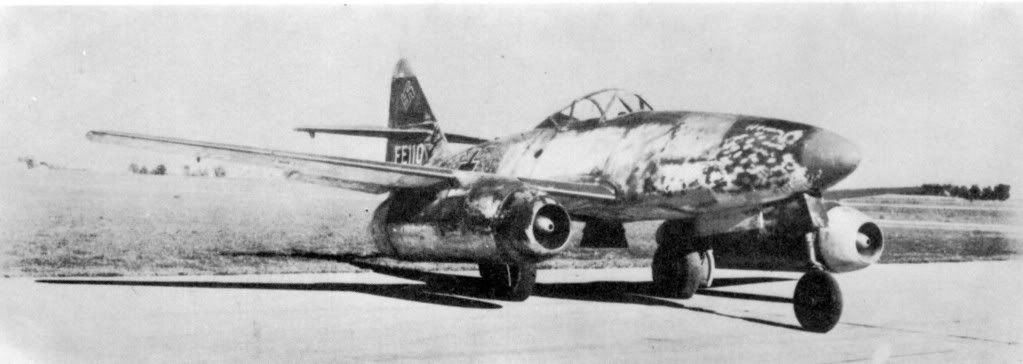
Messerschmitt Me 262 A-1a Schwalbe
Powerplant: 2X Junkers Jumo 004 B1/2/3, 898 kp of static thrust at sea level
Maximum speed: 870 km/h at 6000 m; 827 km/h at sea level)
Armament: 4X30 mm Mauser MK 108, with 100 shells per upper cannon, and 80 shells per lower one
Range: 1050 km at 9.000 m
Service ceiling: 11000 m
Velocity of climb: 1200 m/min.
So far as I can tell from rather a bad drawing…
So sorry for that, my dear Mr. Pdf27. Those are original materials, and they were printed more than sixty years ago, more precisely back there in 1946. I am using those materials only, mostly due to the potential legal complications connected with different copyright issues. In this, as well as in all previous cases, I am completely able to prove that those materials have been borrowed directly from previously publicly presented and unprotected resources.
…that’s a reverse flow heat exchanger such as fitted to the WR-21 marine gas turbine…
Touché, my dear Mr. Pdf 27! Yes, you are right - that really is a counter – flow gas- turbine recuperator. My congratulations.
I will admit however to being stunned if that is what it is, as nobody in their right mind would think to put one on an aero engine - it will be massively too complex, heavy and expensive for any fuel savings you make.
Well… in that case I think that you will be sincerely disappointed, my dear Mr. Pdf 27. You see, I really don’t know what the mental state of the British engineers within Bristol Aero Engines and Armstrong Siddeley Motors Co. really was back there in 1946, but the aforementioned contraption actually was constructed, manufactured, tested and applied in Britain – true, in limited quantity only. They were used only on a Handley Page built two H.P.82 Hermes V passenger aircraft, each having four 2,240 hp turboprops of this type.
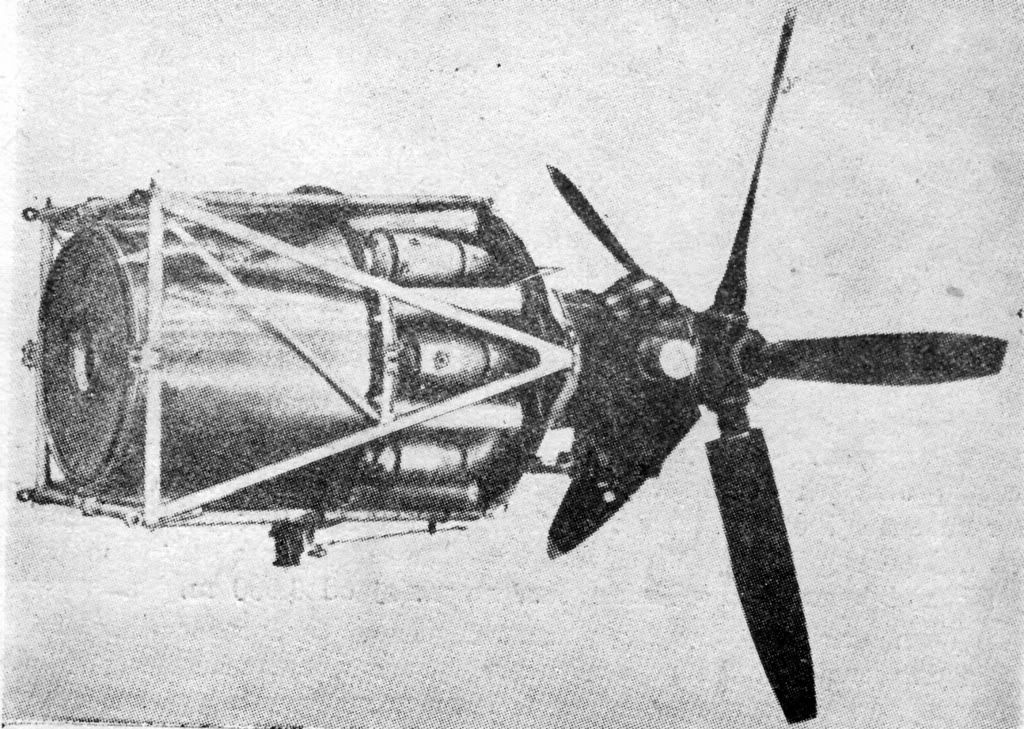
Bristol Theseus I - recuperator-equipped turboprop engine
These engines were previously tested upon an Avro Lincoln testbed and declared as completely suitable for use. Their main mortal sin, however, was their excruciatingly high price.
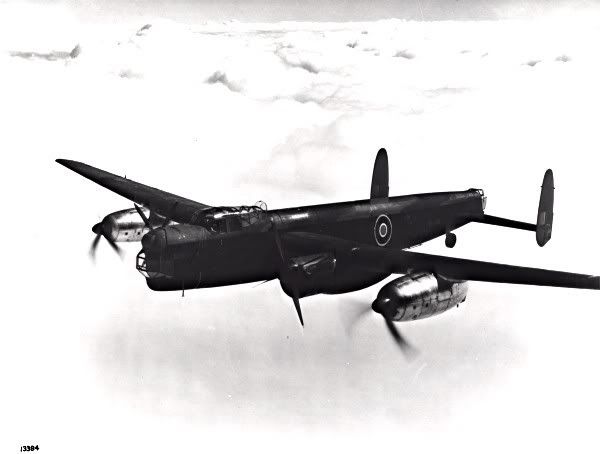
Avro Lincoln Testbed equipped with two Bristol Theseus I
Furthermore, the whole concept has been recently rediscovered. Please, just follow these links:
http://www.mtu.de/en/technologies/engineering_news/intercooled_recuperated.pdf
http://www.asme.org/NewsPublicPolicy/PressReleases/Top_Industry_Executives_Speak.cfm
http://www.aiaa.org/content.cfm?pageid=406&gTable=mtgpaper&gID=62958
Well… It seems to me that the engineering insanity was and still is equally distributed on this planet Earth.
Finally, allow me to take advantage of this occasion once more to express my personal gratitude for your indeed well-expressed and truly matter-oriented posts, my dear Mr. Pdf 27. May the future grant you opportunity and the fulfillment of all your hopes.
And please, don’t worry – I shall answer all those problematic questions, but in this very moment I am waiting for certain factographic materials that –alas! - are still undigitalized and contained in some quite specific, pretty restricted American libraries. In this moment I have to wait for someone who owes me something… but I am sure that soon we will have a very interesting further discussion about this issues.
In the meantime, as always – all the best.
Is nice to see that you are back Librarian. 
Armament:4X30 mm Mauser MK 108, with 100 shells per upper cannon, and 80 shells per lower one
The guns were actually made by Reinhmetall Borsig


Yes, but given the routes they chose not before about 1950!
I’m well aware of the stall/surge problem. What I wasn’t aware of until you mentioned it was that there was any problem with stall/surge (closely related) with centrifugal compressors at all. My notes certainly make no mention of it, while devoting several lectures to stall/surge in axial compressors. This probably indicates the difference in severity of the two.
Hardly - the difference is a few percentage points. The German engines were chronically inefficient anyway due to a lack of Nickel alloys.
How did you work that one out? Alloy availability has everything to do with turbine design and virtually nothing to do with compressor design. The compressors operate cold - a few hundred degrees at most. Standard aerospace aluminium alloys are happy at those temperatures for a few hours, more than long enough given their engine life expectancies.
Loonies. I can see their motivation in trying it (early GTs were horrendous fuel hogs), but recuperators simply don’t gain you very much on an aircraft. The major benefits come at part load, which is why the WR-21 uses it - naval engines spend very little time at full load. Still, you’ve got to remember that all sorts of crazy ideas were tried at the time - take a look at the RR Crecy and Napier Nomad when you get the time.
That’s got both an intercooler and a recuperator on it. Rather a lot of the benefit actually comes from the intercooler.
Quite. I’ve had to deal with far more than my fair share of it at work today 
thank you Librarian i stand corrected about thos power plants it was junkers jumo, just love this site i learn more every time i come on here, thank you
Germany produced more tanks. I’m not sure about ships but Japan appears to have produced far greater tonnage of merchant ships than Germany as well yet Japanese steel production was lower than that of Germany according to all the sources I have seen.
The US had great industrial capacity but it yearly output of weapons increased enormously during the war after starting out at modest levels.
Germany produced more tanks.
That is correct, i dont know in aircraft but Firefley could be right.


I am sorry to have kept you waiting, honorable ladies and gentlemen. Hopefully at this point still is a piece of pie left for me…Thank you for your understanding.
The guns were actually made by Reinhmetall Borsig.
Yes, you are absolutely right, my dear Mr. Panzerknacker. I stand corrected upon that.
Yes, but given the routes they chose not before about 1950!
I am glad that finally we do have the same opinion about something, my dear Mr.Pdf 27.  The only difference in this issue is my certainty that the demarcation line actually is the Year of Our Lord 1948. But that question surely represents a separate theme for another specialized thread…
Hardly - the difference is a few percentage points.
And if those percentage points are representing a total of circa 20000 tons of fuel savings per year I think that the whole thing has to be considered as a completely rational undertaking.
The German engines were chronically inefficient anyway due to a lack of Nickel alloys.
Excellent and utterly correct observation, my dear Mr. Pdf 27! The lack of nickel and chromium alloys really was the main reason for those German engine construction troubles in WW 2. Nevertheless, it has to be mentioned that the most fuel-efficient airplane engine in the WW2 was the German one: Junkers Jumo 205 D, a six cylinder, two-stroke, vertically opposed piston alignment Diesel-engine, that operated with longitudinal scavenging scheme (system Eckelheuser), and powered with fuel oil, represents the engine with the best overall fuel consumption amongst airplane engines in WW2 – remarkable 155 grams of Diesel-oil per produced HP/hour! Its previous variant, Jumo 4, actually was built under a license in Great Britain, and widely known as Napier Culverin.
I know that it sounds almost incredibly, but the second best result amongst airplane engines of the world in WW2 was achieved by a truly remarkable and yet completely forgotten Soviet construction – by a four-stroke, V 12 turbo-supercharged ACh-30 B airplane Diesel engine, that has been constructed by the prodigious engineering genius of Aleksei Dimitrievich Charomsky. Specific fuel consumption in this case was 173.3 g/HP/hour. However, maximal power of this engine was significantly higher: 1500 HP at take-off and with nominal power output of 1300 HP.
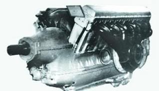
Charomsky ACh-30B
In 1944. however, Charomsky has prepared another, improved variant - ACh-30 BF with the maximum power output of 1900 HP at take off, and 1600 HP nominal combat power.
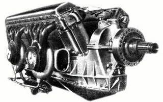
Charomsky ACh-30BF
Loonies
Oh no, my dear Mr. Pdf 27 – they were engineering visionaries, whose pioneering work at the forefront of their fields helped establishment of Britain’s reputation for scientific excellence and true innovation.
How did you work that one out? Alloy availability has everything to do with turbine design and virtually nothing to do with compressor design.
Oh no, my dear Mr. Pdf 27 – on the contrary: availability of one particular, truly unique class of so called Hiduminium alloys is deeply and essentially connected with the design of the British jet-engine compressors. Without those special compressor alloys produced mainly in United Kingdom and USA the whole concept of centrifugal compressor represented a totally unrealizable solution for German engineers. Yes, I know – I have to substantiate my claim. Therefore please permit me a brief evaluation of this highly intriguing question.
As you know, Rolls-Royce engineers have adopted single-stage dual-entry centrifugal compressor with two-sided, hot-forged aluminum alloy impeller, because of intended maximization of air in-soaking within limited air intake cross-section of the engine, as well as because of mutually assured dynamic balancing of axial trust load of the compressor (in this case the diameter of the impeller is reaching only 60 % of a single-sided impeller).
Having a pretty arduous task to hustle 18 kg (1,35 cubic meters) of air per second through the engine, compressor of the Derwent jet-engine was obliged to operate at 16.600 rotations per minute, thus exposing all 58 impeller winglets, (29 winglets on each side), to the rotary speed of 450 m/sec. (above the speed of sound!) and temperature of 227 degrees of Celsius that was encountered in compressor section, with considerable loads arising from centrifugal forces, pressure and winglet-airfoil vibrations excited by the airflow, as well as from erosion emanated due to high-temperature corrosion and thermal cycling fatigue. Rolls-Royce was therefore forced to develop a special stress-resistant aluminum alloy, known as RR 56, that was produced by Armstrong-Sidelley Co. subsidiary, High Duty Alloys Ltd.
This high-strength, precipitation-hardened martensitic aluminum alloy (Al 93.7 %; Cu 2 %; Ni 1.3 %; Mg 0.8 %; Fe 1.4 %; Ti 0.3; Si 0.7 %) actually possessed specific strength properties equal to or exceeding those of some high tensile steel, and as a result has been particularly favored by Rolls Royce engineers due to their constant preference of high strength-to-weight-ratio materials, permitting lightweight but strong mechanical structures.
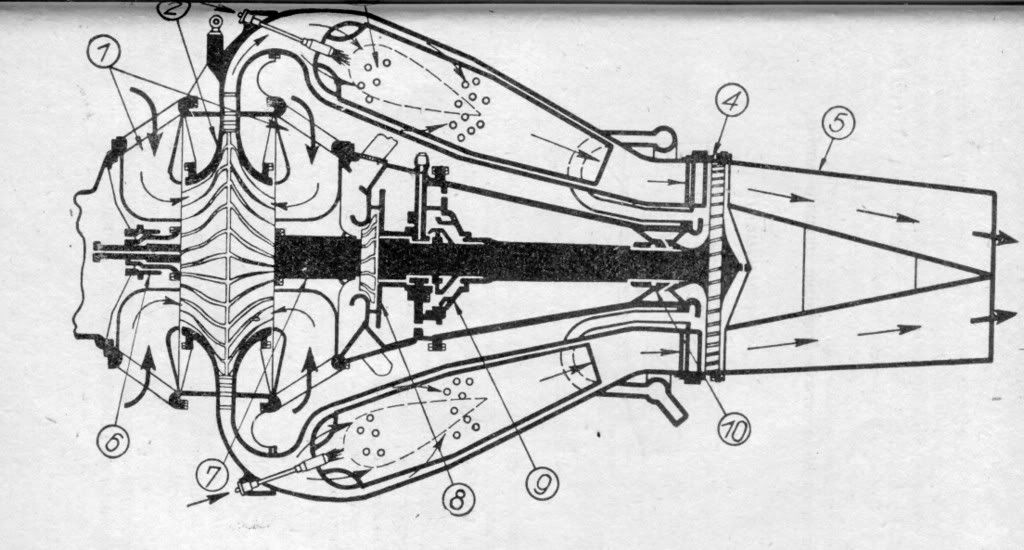
Rolls-Royce Derwent V
Perhaps the best example of those constructive problems and unusual importance of the highly-pressurized air temperature for the light-alloy compressor parts, as well as the role of those special aluminum alloys that actually have been used by Rolls-Royce engineers, is that not so well known fact that all members of the Rolls-Royce Derwent family actually have used specially designed air-cooling for the highly loaded central and rearward engine roller bearings (oh, yes – Derwent engines have used air-cooled constructive elements too!). Considering the fact that the centrifugal compressor actually produced 2 tons of pressurized air in every minute, introduction of separate fan (marked with No. 8 on this scheme), intended for separate low-temperature cooling air procurement, seems as a completely needless constructive exclusivity. But mathematical calculations have demonstrated that previously mentioned high temperature of the compressed air was totally unacceptable for the cooling purposes! Consequently, a separate cooling fan that borrowed 18 HP from the main shaft has been introduced, and the temperature of the pressurized air that has been created in this case was only 30 degrees of Celsius.
On the other hand situation with the axial compressor equipped Jumo 004 engine was totally different. Generating 19.4 kg of compressed air in every second at no more than 8.740 RPM, and with the rotary speed of the compressor blades reduced to sparing 216 m/sec., Jumo 004 elevated the temperature of the pressurized air only to 131 C, thus permitting utilization of more ordinary, different nickel-free aluminum alloys (Almasil, Peraluman and Duralumin), developed and produced by Demag A.G. Duisburg and Dürener Metallwerke A.G. Berlin-Borsigwalde.
As a matter of fact German engineers actually have abundantly applied the so called sequential utilization of different light alloys for various constructive parts of the axial compressor.
For example, stator casement was formed out of Almasil alloy (Al 89.43 %; Si 9.25 %; Cu 0.04%; Mg 0.18 %; Mn 0.36 %; Fe 0.66 %; Ti 0.08%).
Stator blades (first 3 rows only!) have been produced by exploitation of Peraluman alloy (Al 97.3 %; Si 0.94 %; Cu 0.09 %; Mg 0.78 %; Mn 0.68 %; Fe 0.39; Ti 0.08%).
Rotor disc has been manufactured out of Duralumin alloy (Al 93.89 %; Si 0.39 %; Cu 3.12 %; Mg 1.18 %; Mn 0.98 %; Fe 0.26 %; Ti 0.18 %).
Rotor blades, however, were produced by employment of a new member of Duralumin alloy family (Al 94.33 %; Si 0.45 %; Cu 3.04 %; Mg 1.29 %; Mn 0.56 %; Fe 0.29 %; Ti 0.04%).
You will notice that Nickel, that highly deficient metal, is completely absent in all previously mentioned German light alloys.
Sorry, honorable ladies and gentlemen - another forced brake of the post:
The text that you have entered is too long (10813 characters). Please shorten it to 10000 characters long.
Well, never mind…
recuperators simply don’t gain you very much on an aircraft.
Strictly thermodynamically speaking, my dear Mr. Pdf 27, recuperators are always providing greater thermal efficiency and thus better fuel economy of the gas-turbine engine – the rest represents just the question of good or skimpy engineering.
Still, you’ve got to remember that all sorts of crazy ideas were tried at the time - take a look at the RR Crecy and Napier Nomad when you get the time.
Oh, I am assuring you that I do know those magnificent and even today highly intriguing ideas by hart, my dear Mr. Pdf 27. And please - don’t fail to remember those magnificent projects like Beardmore Tornado, Bristol Phoenix, Rolls-Royce Condor, Guiberson Radial Diesel, Packard Diesel, Daimler-Benz 607… my God, the whole generation of unexploited engineering possibilities! And, yes - I have to admit that I still look upon Sir Harry Ricardo as one of the greatest ever born engineering souls on this planet.
Oh yes, I think that this little piece of information deserves a special attention:
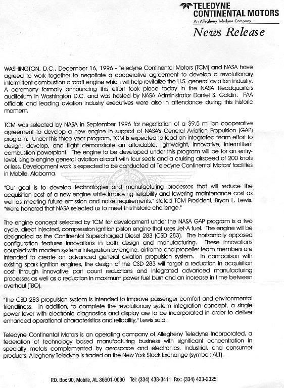
And please – don’t worry: fortunately I was able to find some completely forgotten engineering miracles deeply connected with this specific thematic. 
Rather a lot of the benefit actually comes from the intercooler.
Yes, that is a completely logical concession that was completed to the benefit of the volumetric efficiency of the engine. Unfortunately, airplane engines are not using Bunker C oil, otherwise very suitable for utilizing that recovered heat for vaporization of otherwise greatest number of heat units per gallon containing heavy fuel. But undeniable fact is that recuperator actually is incorporated into the design.
thank you Librarian i stand corrected about thos power plants it was junkers jumo, just love this site i learn more every time i come on here, thank you
Oh, not at all, my dear Mr. Shoogs. Besides, Daimler Benz actually was involved in the German jet-engine program, but that 109-007 project was simply far and away complex for those times and therefore completely inapplicable in WW2.
In the meantime, as always - all the best.
Oh thanks for the excellent posts mst Librarian;)
What airplaine this engine was used for?
Was it for the Pe-8 soviet WW2 heavy bomber?
And do you heared about NK-12MPT the turbo-propeller engine for that was developed for the Ty-95 ( later it was established at the Ty-114 and other)
That amazing engine had a 161 g/HP/hour but the overal power was about 12 - 15 000 HP (!!!) at take of.

Due to its incredible power it was damn loud.
I’m rather a fan of the Napier Deltic myself. That’s one of the few engines with a mad cylinder arrangement that actually made good sense (radical increase in power:weight, which is critical for things like minesweepers).
Surges in gas turbine compressors are not just an altitude problem. I have fabricated a few myself at ground level, one that comes to my memory was one which announced itself with an earshattering and aircraft shaking bang during a confirmation run after an engine change (GE CF6-80) on a Boeing 767. the reson there was that for noise abatement regulations on insistence of the airport company, which had problems with the nimby’s we had to carry out the test run inside an enclosed runup hangar, which was not designed for the intake airflow these massive engines require. As a result a partial vacuum developed in the intake when we pushed the throttles forward, which caused the compressor to surge and eventually stall. We were lucky that we didn’t have to pick compressor blades from the floor behind the engine exhaust. Another one I have seen was a Prat and Whitney PW2040 on a Boeing 757, which surged when the pilot pulled the throttles back from take off power to climb power. At first the pilot thought he had a collision with some light aircraft. When we did a boroscope inspection of the high pressure compressor afterwards, it looked as if somebody had fired a shotgun inside it.
Since centrifugal compressors are normally less surge prone than axial ones, I think the Germans should have encountered this problem first.
Jan
Thank you for your patience, honorable ladies and gentlemen. I hope that I will be able to compensate your kind tolerance.
What airplaine this engine was used for? Was it for the Pe-8 soviet WW2 heavy bomber? And do you heared about NK-12MPT the turbo-propeller engine for that was developed for the Ty-95 (later it was established at the Ty-114 and other) That amazing engine had a 161 g/HP/hour but the overal power was about 12 - 15 000 HP (!!!) at take of.
Yes, my dear Mr. Chevan: Pe-8 (also equipped with another unduly forgotten Soviet Diesel-machine, Yakovlev M-40 F!), Yer-4, Il4, Tu-2 D, all these machines were equipped with those highly intriguing Diesel designs.
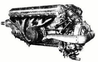
Yakovlev M-40 F
And yes, I am assuring you that I know by hart that superbly powerful, breathtaking Kuznyetsov NK-12, one of the best ever designed turboprop engines on this planet as well as all those undeniable qualities connected with this engine, but…
I think that I have another surprise for you. You see, Soviet engineers actually have developed something that was capable to beat that fabulous previously mentioned fuel economy characteristic of NK 12. And the name of that miracle is OM-127 RN – superb, 8 cylinder, two-stroke, duble-acting conrod-free, liquid cooled turbo-compound airplane Diesel engine, capable to produce 3200 HP of continuous power, with an outstanding power-to-weight (PTW) ratio of 0.635kg/HP, specific power of 145 HP/liter, with the specific fuel consumption of 165 g/HP/hour, and operational ceiling of 12000 meters!
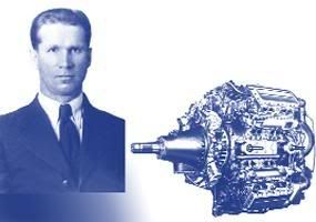
S. S. Balandin – OM-127 RN two-stroke airplane Diesel engine
Perhaps the best illustration of unprecedented complexity of this magnificent engine designed by a team of Soviet engineers that has been led by S. S. Balandin is that previously mentioned double-acting diesel principle. The 2-stroke cycle double-acting engine has a distinct advantage in power output compared with the single-acting type. With twice as many power strokes as a comparable single acting two-stroke engine and, with other conditions being equal, it develops practically twice as much power per cylinder! In addition, the operation is smoother due to the fact that the expansion stroke in one combustion chamber of the cylinder is balanced or cushioned by the compression stroke in the opposite combustion chamber in which the piston is closed at both ends and has a rigid piston rod extending from the lower end. Both ends of the cylinder are closed to form a combustion chamber at each end of the piston! The piston rod extends through the cylinder head of the lower combustion chamber and passes through a stuffing box to prevent leakage of pressure.
In 1951 Balandin and Charomsky have constructed completely new, 24 cylinder X-scheme arranged, two-stroke double-acting, impulse-turbo-supercharger equipped airplane Diesel-engine M 227 that was capable to produce unparalleled 10000 HP at 15000 meters, with a specific fuel consumption of 148 g/HP/hour!
And if you are asking me for the airplane/airplanes that have been intended for utilization of these engines, luckily I was able to find that answer too. This one:
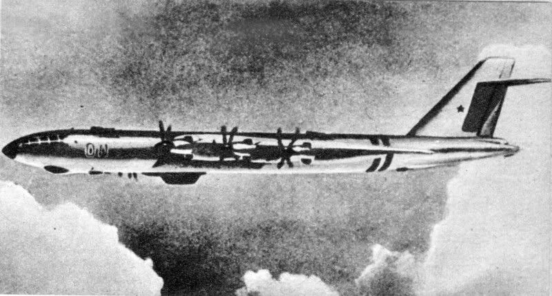
Tupolev Tu-487
Yes my dear Mr. Chevan – completely forgotten Soviet project from 1947. and no, that is not a mistake – it realy has 6 engines.
Librarian - thank you for your highly researched and informative posts.
Oh, not at all, my dear Mr. Arhob1. I am pleased if those informations were useful.
1 - Why was the speed of the Me262 so much higher than the Meteor?
Because of the considerably better aerodynamics, my dear Mr.Arhob1.
Although pretty contained, these informations are completely available for US military personnel, or officially registered and accredited researchers, because USAF actually had compared those airplanes in real tests. Alas, those results are still inaccessible for me, but fortunately I was able to find something in a book “Fluid – Dynamic Drag” by Dr. Ing. Sighard F. Hoerner, that was published back there in 1958. Of course, I have to find another, similar report about Gloster Meteor, but I think that these evaluations (undertaken by official US authorities) are the factual key for this conundrum we share here.
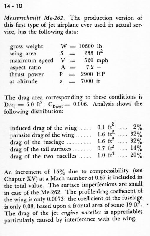
Hoerner, Me 262 drag, op.cit.
Of course, I am shoveling hereinafter…
Another Forced Break of the post, honorable ladies and gentlemen. To be continued…
It appears from the comparison that you posted that the Meteor had much greater range which I presume means the Meteor had a greater fuel laod and weight etc.
No, my dear Mr. Arhob 1 - actually Me 262 was the heavier plane. Here you have the factual comparison (Cristopher Chant : “WW2 – aircraft”, Orbis Publishing Limited London, 1975)
Me 262
Empty weight: 4.420 kg
Loaded weight: 6.400 kg
Max takeoff weight: 7.130
Gloster Meteor F Mk 3
Empty weight: 3.996 kg
Loaded weight: 6.033 kg
Max takeoff weight: unknown 
why did the British go for range and not all out top speed?
Unfortunately, I don’t know, my dear Mr Arhob1. Perhaps they were overwhelmed with a British-made new generation escort-fighter inevitability, or perhaps multi-role airplane necessity. Of course, this is only my personal, completely extraneous speculation.
2 - In the jet engine cutaway diagram you posted why does the combustion products not blow back in to teh compressor?
Because of the of Graham’s law, my Dear Mr. Arhob1 – hot gases are always moving from the area of high pressure toward low pressure areas.
The diffusion or spontaneous intermixture of two gases in contact is effected by an interchange in position of indefinitely minute volumes of the gases, which volumes are not necessarily of equal magnitude, being, in the case of each gas, inversely proportional to the square root of the density of that gas.
And this is the best graphical illustration of the problem that I was capable to find.
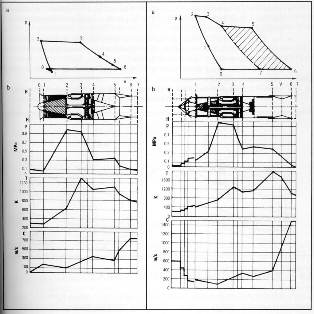
SNECMA - TPV diagram
Just follow that pressure-flow (MPa) curve - everything will be completely comprehensible.
What is the pressure of the air coming from the compressor versus the pressure of the combustion?
I think that this is the most complete answer:
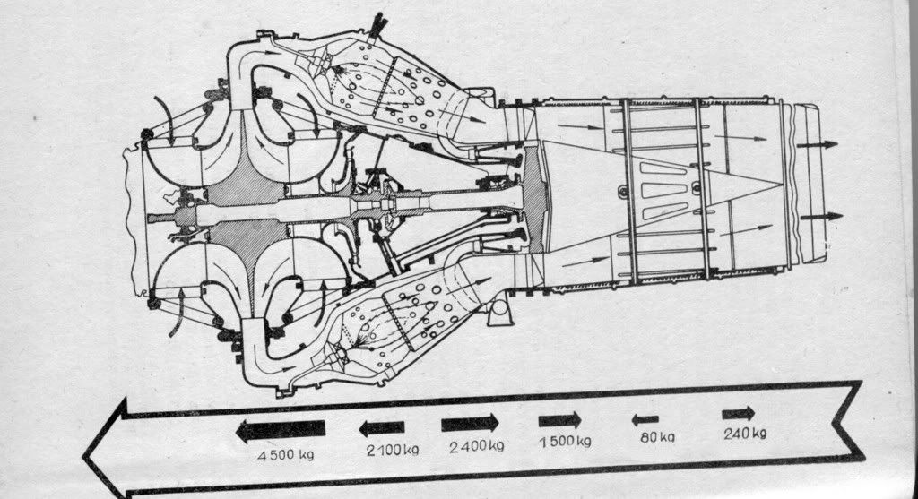
Rolls-Royce Derwent – Engine Pressure Gradient
3 - Did an Me262 ever take on a Meteor on a like for like basis and if so which came out on top?
Unfortunately, my dear Mr. Arhob1 I don’t have suitable materials with reference to this subject and consequently I am utterly incapable to present any relevant information to you.
That’s one of the few engines with a mad cylinder arrangement that actually made good sense
Definitely, my dear Mr. Pdf 27. Although it has to be emphasized that even more sophisticated schema actually has been employed by German engeneers in their Jumo 223 scheme.
And if truth is to be said, another highly intriguing British engine that deserves mentioning is almost completely forgotten Opposed Piston Barrel Engine, based on the so called “Barrel Engine” concept. Such designs date from the 1910’s and consist of a series of parallel cylinders wrapped around a drive-shaft, with the pistons coupled to it through a coupled to it through a swash-plate, cam or a or a wobble-plate.
A variant of this engine specifically designed for aircraft flew in a Simmonds Spartan aeroplane in 1929, and after the WW2 highly talented British engineer Charles Benjamin Redrup, who worked on top-secret armaments projects for the Lancaster and other aircraft, including the hydraulic drive for the spinning “Dam Busters” bombs, have designed more motor-cycle engines and large 1.000 and 2.000 horse-power axial aero engines called “Redrup Radial.”
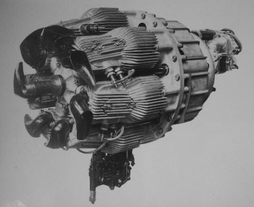
Redrup Fury, Barrel-Piston Engine
More information about this highly intriguing design you will be able to find here:
http://www.fairdiesel.co.uk/Home.html
In the very same time I have to admit that I have my own equally intriguing favorites.
Another forced brake of the post. Well, never mind…
Yeah, if you want very high fuel efficiency two stroke diesel turbo-compound engines are the way to go (the Napier Nomad is another example - postwar British engine, effectively a turboprop with a diesel engine as the combustor section). Problem is that compared to jets they’re very heavy, not terribly well suited for high speed and a maintenence nightmare.
Incidentally, I suspect the reason the early Meteors were slow was simply that they were a rush job to get engines into combat as fast as possible. Performance of the postwar Meteors with engines that weren’t a great deal more powerful tends to bear this out. IIRC the main fixes were lengthened engine nacelles and a different tail
The first one represents one of the most daring engine designs that were constructed in late sixties, by designing team of the most prominent American company - Curtiss-Wright – leaded by an outstanding engineering personality, Dr. Ing. Max Bentele, who was put in charge of the new department for rotary engine development.
Their concept of directly injected stratified charge omnivorous rotary engine (read: Omnivorous Wankel Diesel!), intended for the next generation of US/German joint Main Battle Tank Program (MBT 70 – indeed, one of the most intriguing ever designed combat machines!), as well as for the power supply of the new USN torpedo-vessels, was completely capable to run on JP4, JP5, Diesel-oil or gasoline! This 4-rotor Wankel-engine (Curtiss-Wright RC 4 - 232) that was capable to produce 1100 kW with a weight-total of 843 kg (power-to weight ratio 0.754 kg/kW!), was satisfied with average fuel consumption of 233 g/kW/hour.
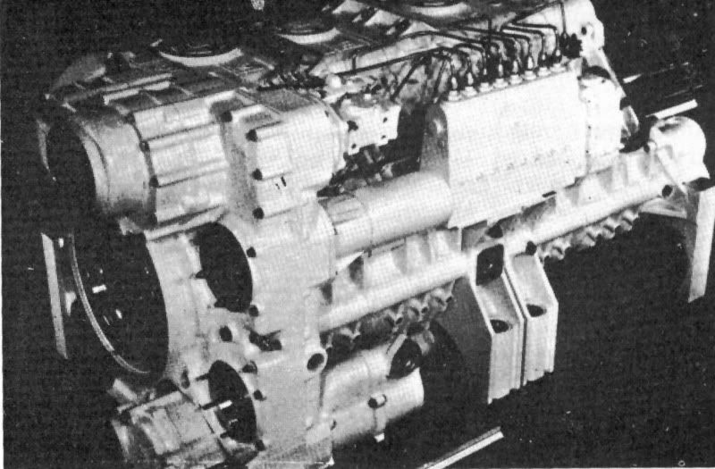
Curtiss-Wright RC 4 -232
Curtiss-Wright was hopeful that these engines will be placed into military use due to their multi fuel abilities, but that huge and promising governmental contract never materialized, which was blamed on conservative marketing of the rotary’s inherent advantages. Nevertheless, this marvelous, highly sophisticated product of human ingenuity that represented a great US firm’s sunset will bear witness to pure, unadulterated engineering genius.
Another engine that outlines the shape of things to come has been designed by a man that in 1937 joined the Junkers Flugzeugwerke, and in next to no time was promoted into the rank of department manager with responsibility for combustion engines development, and especially for the new generation of two-stroke, Shnürle-scheme scavenged Diesel engines.
After the war, in 1957 he presented this tiny, only 9 HP at 3000 RPM producing 2-stroke Diesel engine, outfitted with almost infinitesimal, 350 cm3 combustion chamber displacement, as the very first predecessor capable to effectively shape the outlines of the marvelous engineering things to come – to successfully exemplify the so called adiabatic Diesel engine. And what to hell that means, honorable ladies and gentlemen? Well, perhaps a minuscule disclosure in plain English will be more suitable in this occasion: that small engine designed by the Dr. ing. Ludwig Elsbett actually represented the very first non-cooled Diesel engine on this planet.
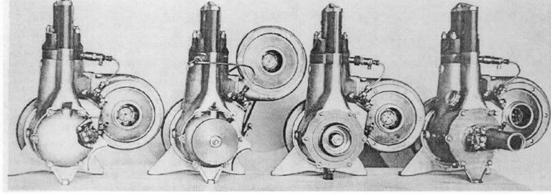
Elsbett Adiabatic Diesel
You see, while in a conventional Diesel-engine, equipped with a pre-combustion chamber, approximately 31% of the energy contained in the fuel is removed from the engine through the cooling system and dispelled into the radiator or in the air, (only 26% in direct injection Diesel-engines!), in the case of the Elsbett-Diesel engine only about 14% to 16% of the produced heat has to be removed, without radiators or cooling fans - simply by the use of previously working exhausts gases. By my personal opinion this tiny engine represents a truthful example of a well-known “Vorsprung durch technik” maxim, that intrinsically German engineering philosophy.
If you are interested for this highly original engineering approach, just follow this link:
http://www.elsbett.com/us/elsbett-diesel-technology/duothermic-combustion-system.html
In the meantime, as always – all the best.
Librarian and PDF, your debate about engines is clearly one of the most fine posting I ever seen here.
However being this a topic about the Messer 262 we should keep the topic in this aircraft and in this case his engines.
We can open a topic exclusively devoted to engines if someone is interested.
Thank you for the amazing infor dear Librarian.
You continie to wonder me of your high detailed engeens posts;)
I’ve never even heared about Tu-487, i’ve read aboutthe manies soviet experimentals aircrafts that were not passed in serial profuction, but about the Tu-487 i was not able to find any inro in the russian net.
Was it a really flight aircraft or it was only the project?
And thanks for the last post engines diagrams.

